The hole in the lower left is the original hole for the vapourized air to blow out of. The large hole under the upper half of the unit is where the upper unit fits into. Within this large hole is the vapour spray atomizing chamber. The long plastic tube coming out of the white wheel, goes down into the water and pulls up water by suctioning. This is the siphon tube and it is spun at a high speed by the electric motor. The water is then sucked up and thrown outwards along the white water wheel against the plastic teeth where it breaks up into spray and vapour which is blown by fan effect out of the vapour hole where the tubeing assembly connects into which delivers the spray mist into the growing chamber attached. wheel.
The hole in the upper right, is the new hole that was drilled with the one inch hole saw (attaches to a regular electric hand held drill). This hole measures one inch across. Underneath the hole is where the old outlet slit was that is now covered by a narrow piece of white plastic (glued on).
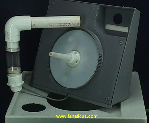
The water vapour delivery tubing assembly is on the left side. On the bottom is a male screw adapter with a female connection (for 3/4" tubeing!!!!!). Next is a small piece of thin wall 3/4" tubeing connected to a piece of clear polyethelene hose with an internal diameter of around one inch. This connects the two halves of the vapour delivery assembly and also provides a way to adjust the angle of the tubeing. This is very important. This lets you adjust it to fit whatever you are rigging up. Without it, you are stuck with a rigid assembly that is difficult to make fit.
Next comes the 3/4" inch elbow connector. At the poly hose side is a small piece of 3/4" tubeing. You can adjust angles here also. Out the end of the elbow connector is the outlet tube which fits into your chamber however you want to make it work.
Psylocybe fanaticus
October 1998
Seattle Washington